Considerable Parameters
VIC-II
- accurate Color generation (YUV/YIQ en- and decoding)
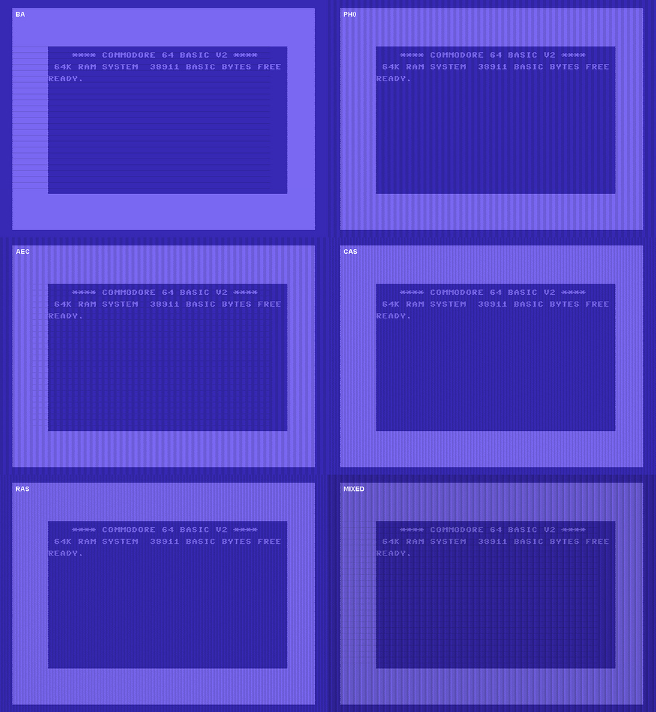
- (not only) "AEC Line" Glitch
- RF-Modulator/Video Amplifier Characteristics (which are responsible for the so called "black bleeding")
- HMOS "Grey Dot" Glitch
Video System
- Bandwidth Limitation for Luminance and Chrominance Signals
- PAL: Delayline and Odd/Even lines color mixing
- Composite: Chroma/Luma Interference (the famous red/green colums) (not yet)
- RF-Video: (not yet)
Monitor
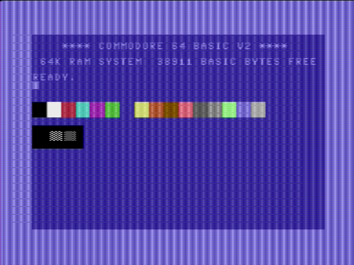
- Scanlines (in 2x Renderer)
- RGB Subpixel Texture (in 3x Renderer)
- Blooming (not yet)
- White Smear (not yet)
- Phosphor Persistance (not yet)
Video Timing
| PAL-B/G | NTSC-M | |
|---|---|---|
| frame freq | ~50 Hz | ~60 Hz |
| gamma | 2,8 | 2,5 |
| line freq | 15625 Hz | 15734 Hz |
| video bandwidth | 5,0 MHz | 4,2 MHz |
| color bandwidth | I: 1,3 MHz, Q: 0,4 MHz | |
| color subcarrier | 4,43361875 MHz | 3,57954545 MHz |
| VIC-II pixel clock | 7,882 MHz | 8,18184 MHz |
| VIC-II color clock | 17,734472 MHz | 14,31818 MHz |
| C64 CPU clock | 0,985248 MHz | 1,02273 MHz |
| C64 Cycles per line | 63 | 65 |
| VIC-II total lines | 312 | 263 |
Color Spaces
|
|
YCbCr
| RGB to YCbCr | YCbCr to RGB |
|---|---|
Y = 0,2989 * R + 0,5866 * G + 0,1145 * B Cb = B - Y Cr = R - Y |
G = Y - (0,1145 / 0,5866) * Cb - (0,2989 / 0,5866) * Cr B = Cb + Y R = Cr + Y |
| YCbCr to YUV | |
|---|---|
U = 0,493111*Cb V = 0,877283*Cr |
YUV (PAL)
YUV (CCIR 601) is the PAL colorspace. It's a slightly modified YCbCr for better broadcasting.| RGB to YUV | YUV to RGB |
|---|---|
Y = 0,299 * R + 0,587 * G + 0,114 * B U = -0,147 * R - 0,289 * G + 0,436 * B (B-Y;Cr) V = 0,615 * R - 0,515 * G - 0,100 * B (R-Y;Cb) |
R = Y + 0,000 * U + 1,140 * V G = Y - 0,396 * U - 0,581 * V B = Y + 2,029 * U + 0,000 * V |
YIQ (NTSC)
NTSC uses the YIQ colorspace. Compared to YUV, YIQ is rotated by 33 degr clockwise, which results in different bandwidth for the color components (I: 1300 kHz, Q: 400 kHz)| RGB to YIQ | YIQ to RGB |
|---|---|
Y = 0,299 * R + 0,587 * G + 0,114 * B I = 0,596 * R - 0,274 * G + 0,322 * B Q = 0,212 * R - 0,523 * G - 0,311 * B |
R = Y + 0,956 * I + 0,621 * Q G = Y - 0,272 * I - 0,647 * Q B = Y - 1,105 * I + 1,702 * Q |
| YIQ -> RGB (FCC sanctioned decoder matrix) | YIQ -> RGB (Sony CXA2025AS US decoder matrix) |
|---|---|
R = Y + 0,946882 * I + 0,623557 * Q G = Y - 0,274788 * I - 0,635691 * Q B = Y - 1,108545 * I + 1,709007 * Q |
R = Y + 1,630 * I + 0,317 * Q G = Y - 0,378 * I - 0,466 * Q B = Y - 1,089 * I + 1,677 * Q |
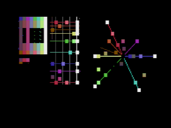
VIC-II Colors
- Peptos Commodore VIC-II Color Analysis
- OpenOffice calc sheet for own experiments
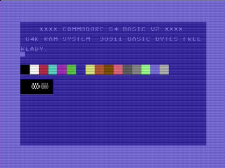
NTSC
especially NTSC users approached me a lot in the past, mentioning that the colors generated by VICE don't quite match what they know from the real thing. some possible causes which are addressed here are:- TVs and Monitors manufactured "later" may use an optimized NTSC decoding matrix (resulting in somewhat more "vibrant" colors)
- appearently NTSC VIC-IIs exist which use a slightly different color set (most noteably the much more distinctive purple)
 NTSC |
 NTSC (old lumas) |
 SONY CXA2025 |
 SONY CXA2025, alternative color set |
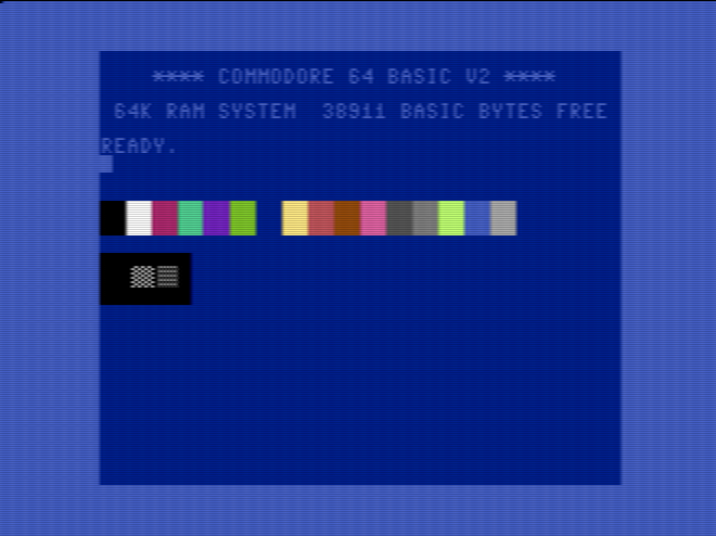
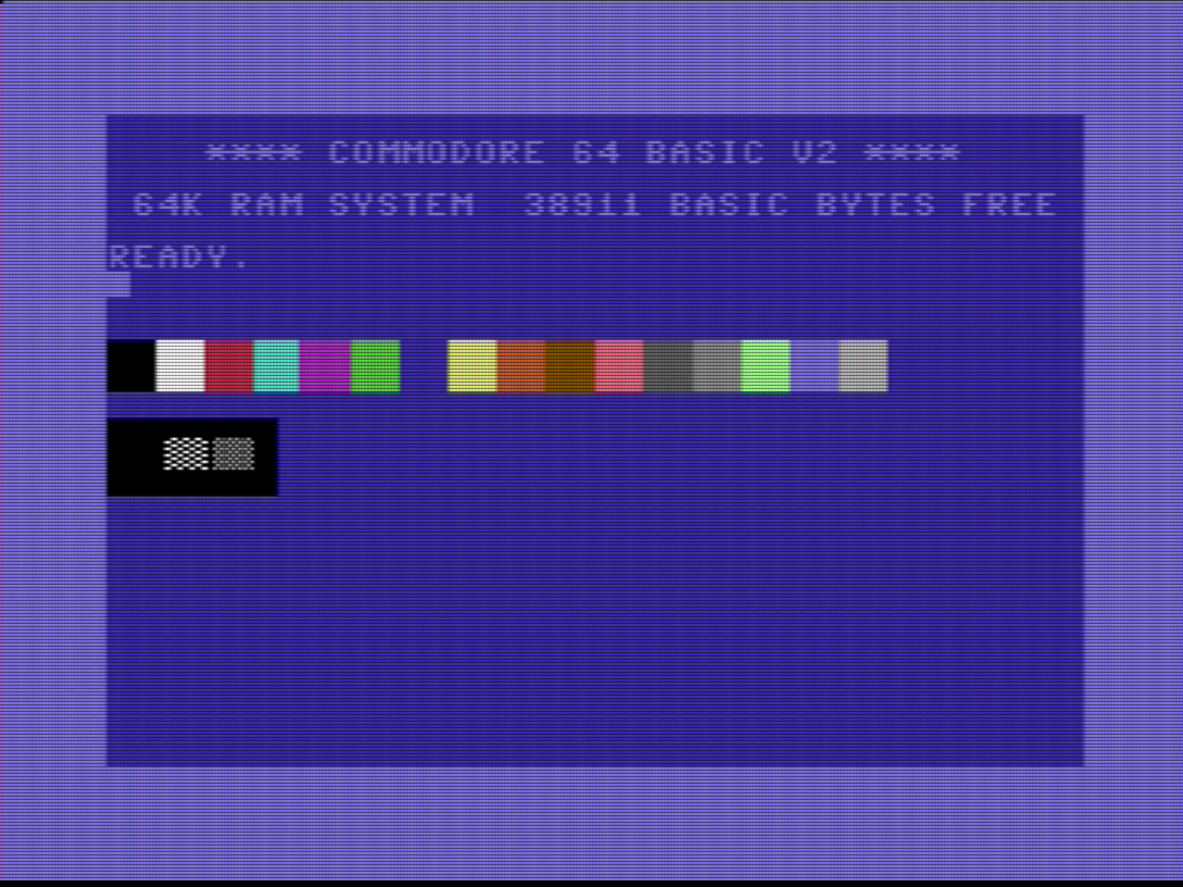
PAL
generally for PAL the colors are more defined and stable, so the above should generally give you colors which are pretty close to what you expect from the real thing: PAL |
 PAL (old lumas) |
AEC Line Glitch
|
Somehow the activity of various signals, most noteably the AEC line, is coupled into the Luma Output, the result is
that the current slope of those lines is visible (added to?) in the luma signal.
For example, a rising edge of the AEC signal produces a tiny bit more luma (for about
one pixel) and a falling edge produces an even less tiny bit less luma (for about two pixels).
This artefact is drastically exagerated here (obviously). On most real setups the brighter lines are barely visible (they become more visible if you decrease saturation). The darker lines are usually hardly visible at all, except on modded C64s that have their RF-Modulator removed for better picture quality. |
 |
 | |
| picture provided by ZeroX |
RF-Modulator/Video Amplifier Characteristics
This effect was attributed to the NMOS output drivers in the past, but that has been
proven wrong - C64s that have their RF-Modulator removed do not show this artefact, which
means it is produced by the circuit in the RF-Modulator. It can be roughly described by
the following rules:
|
 |
Connection
 svideo (default) |
 composite |
PAL Decoding
in PAL the color signal is always mixed with that of the previous scanline. this has the following consequences:
|
 |
| another Artefact of PAL decoding is that Saturation is slightly different every other line (exagerated here). | 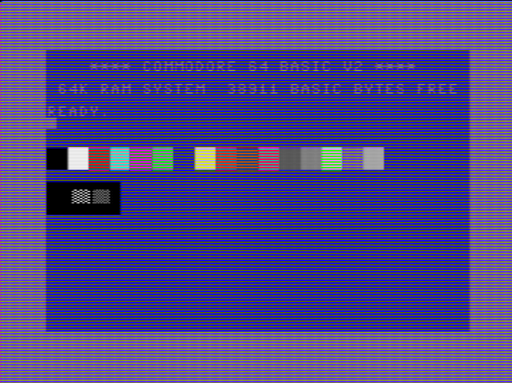 |
NTSC Decoding
 | default |
 | SONY CXA2025 |
Artefact Color
these are the most interesting bits for us from this usenet posting:|
FWIW, my "folk hypothesis" growing up was to consider the horizontal signal
to be divided into [R][G][B] sub-pixels, and Apple screen bits to be
approximately a half-pixel wide, e.g. [0][0] is the same width as [R][G][B].
The bit-7 shift would offset things so the same two bits [0][0] would
overlap the neighboring [G][B][R] subpixels instead. A pattern of [1][1]
would light up RGB (==white). A pattern of [0][1] would light up mostly
[B]=blue and [1][0] would light up [R][G]=orange, or with the bit-7 shift
[0][1] would light up [B][R] = violet and [1][0] would light up mostly [G] =
greeen.
Now I *know* that NTSC does not address individual pixels, but my "folk-hypothesis" was remarkably effective so it burnt into my brain. Looking at page 96, I see that it's strangely almost correct - there are 180 cycles across the screen of a color signal which goes through the spectrum MROYGCBV, and if the monochrome signal is "on" in a particular field of that you get those colors; Apple's pixels do address half of one of these cycles each. So [0][1] lights up GCB=green, [1][0] lights up MRO = purple. Shift a little bit over and you get. [0][1] lighting up CBV=blue and [1][0] lighting up ROY=orange. This also explains the "fringing" rather nicely. The pattern [0][0][1][1][0][0] which in (Apple Hi-Res)theory is perfect black-white-black will inevitably have the "white" signal "leaking" to either magenta or yellow on the edges depending on where it is within the cycle. |
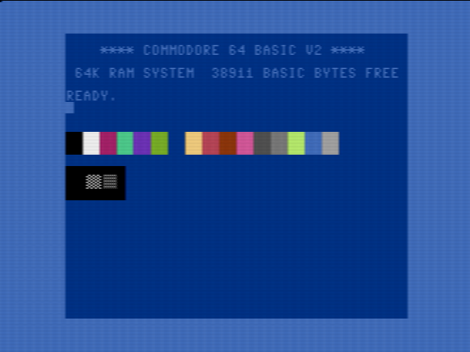
Visible Area
Different monitors show differently much of the VIC's output. The following figures give the maximum possible numbers:PAL-B
- The left border is 6 chars wide. From these 48 pixels, 2 are invisible because of the white HSYNC burst stripe.
- The right border is 4,5 chars wide, which is 36 pixels.
- Thus, the visible area is 46 + 320 + 36 = 402 pixels wide.
- The earliest line known to be displayed by any monitor is $08. This makes 43 lines of upper border.
- The last line known to be displayed is $12c, which makes 49 lines of lower border.
- Thus, the visible area is 43 + 200 + 49 = 292 pixels high.
Overall, this makes a maximum visible area of 402 by 292 pixels.
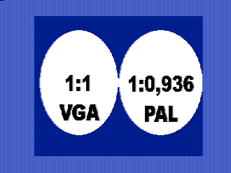
Aspect Ratio
The VIC's pixels are not actually square. The actual aspect ratio can be calculated as follows:
PAL-B
- For a 1:1 really square pixel, a pixel clock of 14,75 MHz is needed. Without interlacing, like the VIC
does, half of it, i.e., 7,375 MHz.
- The C64 is clocked at 0,985250 MHz, where 8 pixels are drawn each cycle, which makes a pixel clock
of 0,985250 MHz * 8 = 7,882 MHz.
- That makes 7,375 / 7,882 = 0,936, so the pixel aspect ratio is 0,936:1.
This means that the pixels are a bit higher than they are wide.
Another, but less accurate, way of calculating the pixel aspect ratio is the following:
- The VIC outputs 372 by 292 visible pixels on a 4:3 screen.
- ((372 / 292) / 4) * 3 = 0,955, which makes a pixel aspect ratio of 0,955:1.
- For a 1:1 really square pixel, a pixel clock of 14,75 MHz is needed. Without interlacing, like the VIC does, half of it, i.e., 7,375 MHz.
- The C64 is clocked at 0,985250 MHz, where 8 pixels are drawn each cycle, which makes a pixel clock of 0,985250 MHz * 8 = 7,882 MHz.
- That makes 7,375 / 7,882 = 0,936, so the pixel aspect ratio is 0,936:1. This means that the pixels are a bit higher than they are wide.
- The VIC outputs 372 by 292 visible pixels on a 4:3 screen.
- ((372 / 292) / 4) * 3 = 0,955, which makes a pixel aspect ratio of 0,955:1.
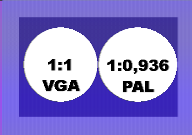 |
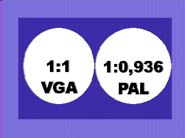 |
 |
| PAL Image, 1:1 Aspect Ratio | PAL Image, PAL Aspect Ratio | NTSC Image, PAL Aspect Ratio |
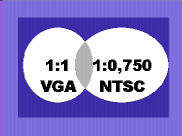
NTSC
- NTSC square pixels 12,272727 MHz /2 = 6,1363636 Mhz
- NTSC pixel clock 1,02273 MHz * 8 = 8,18184 Mhz
- 6,1363636 / 8,18184 = ~ 0,75
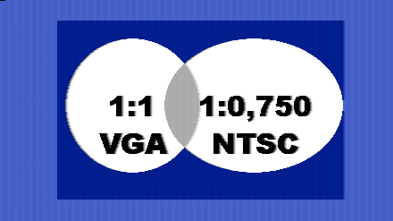 |
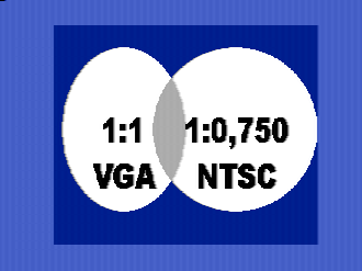 |
 |
| NTSC Image, 1:1 Aspect Ratio | NTSC Image, NTSC Aspect Ratio | PAL Image, NTSC Aspect Ratio |
Scaling
 x1 |
 x2 |
 x3 |
References
general Theory
- Color FAQ
- Gamma FAQ
- interactive digital filter design
- analog Video basics
- colour encoding Details
- PAL SECAM NTSC Conversion
PAL
NTSC
- Wapedia
- YIQ Colorspace on Wikipedia
- NTSC Video Info on nesdev Wiki
- NES colors Discussion in nesdev Forum
- Wikipedia
VIC-II
other simulation efforts
- Blargg's NTSC libraries
- analogtv xscreensaver module
- Blur and Bleed: Running Games on a TV
- CRT Emulation for the Atari VCS
- Cathode - a terminal emulator for OSX featuring monochrome CRT emulation
- OpenEmulator - an emulator framework (currently supporting apple2) featuring accurate PAL/NTSC and CRT emulation
- Micro64 - a C-64 emulator with excellent CRT Emulation.
- Altirra - a Apple2 emulator with CRT Emulation.